
As an electrical engineer, I’m often asked by friends: “Why do problems keep popping up with my home wiring/this equipment even after the wires are connected?” More often than not, the root cause isn’t the wires themselves, but that small yet crucial connecting component—the copper cable lug.
Think of it as the “joint” or “handshake” in your circuit. A firm, reliable “handshake” is the foundation for smooth energy transfer; a loose or faulty one can cause anything from unstable signals and device reboots to severe overheating and even fire hazards.
Today, we’ll thoroughly understand how to properly select this seemingly insignificant “small part.”
Simply put, a cable lug is a metal sleeve designed to ensure a reliable connection between wires and equipment such as circuit breakers, contactors, or terminal strips.
• Poor mechanical strength: Vibration or pulling can easily loosen the connection.
• Oxidation and corrosion: Copper wires exposed to air oxidize, forming copper oxide with poor conductivity that increases resistance.
• Poor contact: Twisting multi-strand wires together makes it difficult to fully compress all internal strands, resulting in a small actual contact area. This increases resistance, causes heating, sparks, and may even lead to fires.
• Equipment damage: Forcing loose copper strands into terminal holes may expose some strands, causing short circuits or damaging equipment terminals.
Specialized copper terminals, however, perfectly resolve all these issues through the crimping process.
Selecting terminals is like matchmaking—it must be “compatible.” Remember these five key points, and you’ll become a selection expert.
This is the most crucial factor! The terminal’s current rating must be greater than or equal to the maximum continuous current that may flow through the circuit.
Practical Example: Quick Selection Guide
Suppose you need to configure power cables and terminals for an 8.5kW instantaneous electric water heater, with a household voltage of 220V.
1.Calculate current: 8500W / 220V ≈ 6A.
2.Selecting the wire: According to electrical engineering rules of thumb or cable current-carrying capacity tables, a 6mm² copper core wire has a safe current-carrying capacity of approximately 48A under exposed installation conditions, which meets the requirement.
3.Selecting terminals:
Current Rating: The terminal’s rated current must be ≥ 38.6A. Referring to the product catalog, a standard 60A terminal fully meets this requirement while providing ample margin to prevent overload.
Wire Gauge Matching: This 60A terminal must also be marked as suitable for 6mm² cable.
Type Selection: For fixed appliances like water heaters, OT (ring) terminals are recommended (as shown in Figure 1). These slip over screws and are secured with nuts, providing the most robust connection resistant to vibration-induced loosening.
Quick Tip: When uncertain, err on the side of larger size. Using a 60A terminal for 10A wire is fine, but using a 10A terminal for 60A wire is a disaster waiting to happen.

Wire Gauge vs. Rated Current Reference Table (Copper Wire)
| Nominal Wire Cross-Section (mm²) | American Wire Gauge (AWG) | Approximate Wire Diameter (mm) | Reference Rated Current (A) | Common Applications for |
| Small-Cross-Section Wires (0.5–6 mm²) | ||||
| 0.5 | 20 | ≈0.8 | ~3 | Signal wires, control circuits |
| 0.75 | 18 | ≈1.0 | ~6-7 | Lighting circuits, small appliances (e.g., desk lamps) |
| 1.0 | 17 | ≈1.1 | ~10 | – |
| 1.5 | 16 | ≈1.4 | ~15-16 | Household outlet circuits, main lighting circuits |
| 2.5 | 13 | ≈1.78 | ~20-25 | Air conditioner dedicated outlets |
| 4 | 11 | ≈2.2 | ~25-32 | Air conditioner units, instant water heaters |
| 6 | 9 | ≈2.78 | ~32-40 | Main service bus, central air conditioning, electric water heater |
| Medium-cross-section wires (10-70mm²) | ||||
| 10 | 7 | ≈3.6 | ~50-60 | Residential main circuit breaker, |
| 16 | 5 | ≈4.5 | ~68-80 | Small three-phase motors, villa service lines |
| 25 | 3 | ≈5.6 | ~89-106 | Large three-phase motors, factory power distribution trunk lines |
| 35 | 2 | ≈6.7 | ~110-130 | Factory workshop power distribution |
| 50 | 1/0 | ≈8.0 | ~135-160 | Main distribution panels, high-current busbars |
| 70 | 2/0 | ≈9.4 | ~170-200 | Main distribution panels for large buildings, high-power equipment |
| Large-cross-section conductors (95-240mm²) | ||||
| 95 | 3/0 | ≈11.0 | ~210-240 | Building complex power distribution |
| 120 | 4/0 | ≈12.4 | ~240-280 | Area power supply trunk lines, substation outgoing lines |
| 150 | – (AWG 250kcmil) | ≈13.8 | ~280-320 | Industrial park power supply, large transformer connections |
| 185 | – (AWG 350kcmil) | ≈15.4 | ~330-370 | Urban underground cable networks, main power tunnels |
| 240 | – (AWG 500kcmil) | ≈17.5 | ~390-440 | Main feeder lines for large factories |
| Extra-large cross-section conductors (300–630 mm²) | ||||
| 300 | – (AWG 600kcmil) | ≈19.6 | ~450-505 | Urban transmission and distribution networks |
| 400 | – (AWG 800kcmil) | ≈22.6 | ~530-600 | Primary power transmission corridors |
| 500 | – (AWG 1000kcmil) | ≈25.2 | ~610-680 | Ultra-large data center feeders, heavy industrial sites |
| 630 | -(Greater than AWG 1000kcmil) | ≈28.3 | ~700-775 | Power plant outlets, power grid backbone lines |
The terminal’s “butt” (conductor tube) must perfectly match the cable diameter you’re using.
Below are the most common types:
Application: Universal terminals for connecting wires/cables to equipment.
Features: Multiple hole sizes (M3/M4/M5, etc.), standardized dimensions. Common Applications: Low-voltage distribution, equipment terminals, home appliances.
For household and most industrial applications, high-quality tin-plated copper terminals are entirely sufficient.
Choosing the right terminal is useless if crimping is done poorly.
Crimping Procedure

What is the current rating? -> Determine the terminal’s current rating
What is the wire gauge? -> Determine the terminal’s wire diameter rating
What equipment is it connected to? -> Determine the terminal head type and model (OT/UT/DTL, etc.) and screw hole size
What environment will it be used in? -> Determine if special plating (e.g., nickel-plated) is required
Follow this process step by step, and you’ll precisely find the perfect “it.”
In electrical connections, “close enough” is “far from sufficient.” A low-cost terminal protects equipment worth thousands and safeguards critical safety.
Never let small savings lead to big losses!!
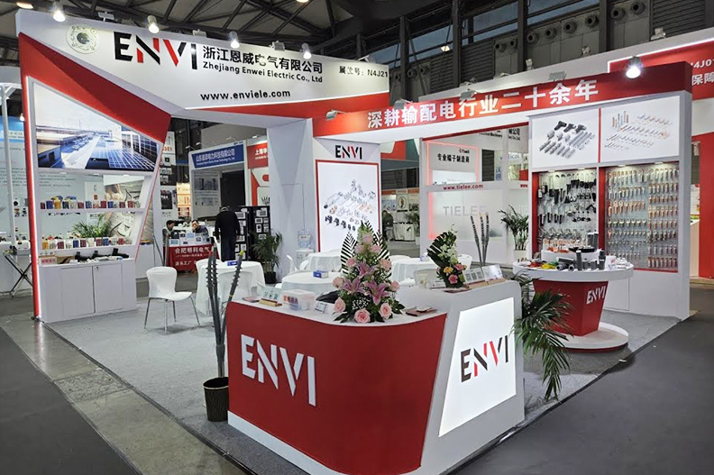
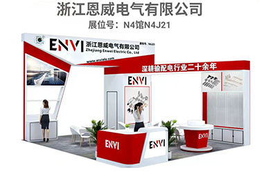
With extensive experience, excellent craftsmanship, and superior customer service, we meet various technical requirements to satisfy our customers and have gained widespread